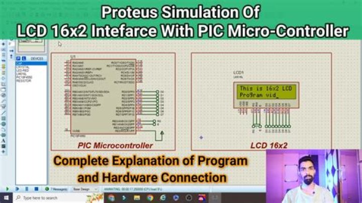
16X2 LCD Interfacing PIC Microcontroller – Circuit Explanation: The resistor R1 is used for giving the contrast to the LCD. The crystal oscillator of 12 MHz is connected to the OSC1 and OSC2 pins of Pic microcontroller PIC18F4550 for system clock. The capacitor C2 and C3 will act filters to the crystal oscillator.
What is LCD in PIC microcontroller?
16×2 Character LCD is a very basic LCD module which is commonly used in electronics projects and products. It contains 2 rows that can display 16 characters. Each character is displayed using 5×8 or 5×10 dot matrix. A microcontroller needs to send two informations to operate this LCD module, Data and Commands.
What is PIC 16f887?
PIC16F887 Microcontroller is an 8-bit microcontroller designed with RSIC CPU technology, which helps the microcontroller to give the maximum output using less power. It has a total of 40-pins and all these pins come in multiple packages to solve the requirement of small and modern circuits.
How do you interface LCD with PIC microcontroller what is the starting address of line 1?
The first line addresses are from 00 to 27, the second line addresses start from 40 to 67 in hexadecimal. To move the cursor to the beginning of second line, the DDRAM address will be 0x40. For LCDs with more than 2 lines, please check their datasheet for more information….Interfacing LCD Display With PIC Microcontroller – XC8.
| Instruction | Byte |
|---|---|
| Shift display right | 0x1C |
When connect LCD to PIC the number of PIC pins that connected in 8 bit mode are?
A character LCD can be configured in 8 bit or 4-bit mode in which 8 data pins and 4 data pins are used respectively. This feature allows efficient use of the digital I/0 pins of the microcontroller.
What is LCD in embedded system?
An LCD (Liquid Crystal Display) is a standard display device for hand-held embedded systems. An LCD display system is composed of an LCD panel, a frame buffer memory, an LCD and frame buffer controller, and a backlight inverter and lamp.
How do I use MikroC Pro for photos?
How to Use “MikroC PRO for PIC” to Program PIC Microcontrollers
- Why use MikroC Compiler?
- Download MikroC Pro Compiler.
- Create New Project with MikroC. Set Configuration Bits.
- Write Your First Program.
- Example Code MikroC.
- Compile Code with MikroC.
- Proteus Simulation.
- Video lecture on how to use MikroC for pic.
What is Lcd_rs?
LCD_RS: Register Select (data/instruction) signal pin. LCD_EN: Enable signal pin. LCD_D7_Direction: Direction of the Data 7 pin. LCD_D6_Direction: Direction of the Data 6 pin. LCD_D5_Direction: Direction of the Data 5 pin.
How to configure the LCD module of pic16f887 microcontroller?
In this project the PIC16F887 microcontroller runs with its internal oscillator @ 8 MHz, MCLR pin is configured as an input pin. after the download, add the library file ( LCD_Lib.c) to project folder. LCD_Begin (); // must be called before any other function, it initializes the LCD module.
What is the maximum number of ADC channels in pic16f887?
ADC in PIC16F887 microcontroller PIC16F887 uses a 10-bit ADC module to convert an analog signal into binary form. So the maximum count that can be obtained is 2^10 which gives 1024. It consists of 14 Analog channels (AN0-AN13).
What is the use of LCD_init() and LCD_clear() functions?
Lcd_Init () : This function will initialize the LCD Module connected to the following defined pins. These connections must be defined for the proper working of LCD. Lcd_Clear () : To clear the display. Lcd_Set_Cursor (int row, int column) : This function is used to set row and column of the cursor on the LCD screen.
How to control LCD using MPLAB xc8 compiler?
For controlling LCD using MPLAB XC8 compiler we need to know the hardware of LCD. These LCDs commonly uses HD44780 compliant controllers. So we need to learn HD44780 Dot Matrix LCD Controller Datasheet. Don’t worry we already developed an LCD library including commonly used functions, so you can use it without any hardware knowledge of LCD.