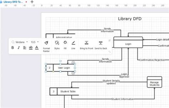
Data Flow Diagram (DFD) depicts the flow of information and the transformation applied when a data moves in and out from a system. The overall system is represented and described using input, processing and output in the DFD.
What is DFD level?
DFD levels are numbered 0, 1 or 2, and occasionally go to even Level 3 or beyond. The necessary level of detail depends on the scope of what you are trying to accomplish. DFD Level 0 is also called a Context Diagram. It’s a basic overview of the whole system or process being analyzed or modeled.
What Level 0 DFD explains?
Level 0 DFDs, also known as context diagrams, are the most basic data flow diagrams. They provide a broad view that is easily digestible but offers little detail. Level 0 data flow diagrams show a single process node and its connections to external entities.
What are the types of DFD?
DFD is of two types:
- Logical DFD: Logical data flow diagram mainly focuses on the system process. It illustrates how data flows in the system.
- Physical DFD: Physical data flow diagram shows how the data flow is actually implemented in the system. Physical DFD is more specific and close to implementation.
How do I get a Level 1 DFD?
Constructing level 1 DFDs
- Identify processes.
- Draw the data-flows between the external entities and processes.
- Identify data stores by establishing where documents / data needs to be held within the system.
- Add data-flows flowing between processes and data stores within the system.
- Check diagram.
How many types of DFD are there?
Including more than nine processes on a data flow diagram. are the same for all DFDs, there are three main types of data-flow diagram: Data-Flow Diagrams 4 • Context diagrams — context diagram DFDs are diagrams that present an overview of the system and its interaction with the rest of the “world” .
How do you draw a Level 0 and 1 DFD?
Draw the level zero dfd.
- Draw external entities near edges of the diagram.
- Draw and label flows to and from external entities (leave the center blank).
- Draw internal flows. Remember that each process bubble must have input(s) and output(s).
Is DFD a UML diagram?
A DFD is a graphical representation of how the data flows through a system, while UML is a modeling language used in object oriented software design. Therefore the UML diagrams, when combined represent a more detailed view of a system than using the DFD alone.
What is the difference between physical and logical DFD?
What’s the difference between a logical DFD and a physical DFD? A logical DFD focuses on the business and business activities, while a physical DFD looks at how a system is implemented. The logical DFD describes the business events that take place and the data required for each event.
What are the four basic elements of DFD?
All data flow diagrams include four main elements: entity, process, data store and data flow.