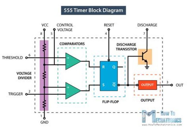
The output is either low, which is very close to 0V, or high, which is close to the supply voltage that’s placed on pin 8. The output pin is where you would connect the load that you want the 555 timer to power.
What is a voltage controlled oscillator (VCO)?
A voltage controlled oscillator is an oscillator whose frequency is controlled by an input voltage. Basically, the voltage input into the VCO chip controls how many times a digital signal will oscillate in a given time period. We’ve already shown how to build a voltage-controlled oscillator with a 4046 phase-locked loop chip.
How do you increase the frequency of a VCO?
This VCO offers a wide range of frequencies. When the voltage is high, the frequency is low. As we decrease the voltage to the control voltage pin, the frequency increases. Additionally, if you want to increase the frequency of the output signal, you can decrease either the resistor or capacitor in the RC network.
The standard TTL 555 can operate from a supply voltage between 4.5 volts and 18 volts, with its output voltage approximately 2 volts lower than its supply voltage VCC. The 555 can source or sink a maximum output current of 200mA, (but it may get hot at this level), so the circuit variations are unlimited.
What is the value of time period of a 555 multivibrator?
Astable Multivibrator using 555 – Design Theory The time during which the capacitor C charges from 1/3 VCC to 2/3 VCC is equal to the time the output is high and is given as tc or THIGH = 0.693 (RA + RB) C, which is proved below.
What Is pin number 8 in 8 pin IC 555?
| Pin | Name | Description |
|---|---|---|
| 6 | threshold | Detects when the voltage on the timing capacitor rises above 0.66 Vcc and resets the output when this happens. |
| 7 | discharge | Provides a discharge path from the timing capacitor to ground when the output is low. |
| 8 | Vcc | Positive power supply voltage. |
Where are 555 timers used?
The 555 timer chip is extremely robust and stable 8-pin device that can be operated either as a very accurate Monostable, Bistable or Astable Multivibrator to produce a variety of applications such as one-shot or delay timers, pulse generation, LED and lamp flashers, alarms and tone generation, logic clocks, frequency …
How to use 555 timer astable calculator?
In this 555 timer Astable calculator, enter the values of timing capacitor C and timing resistors R1 & R2 to calculate the frequency, period and duty cycle. Here the time period is the total time it takes to complete one on/off cycle (T 1 +T 2), while Duty cycle is the percentage of total time for which the output is HIGH.
What is the minimum output time delay for a 555 timer?
A Monostable 555 Timer is required to produce a time delay within a circuit. If a 10uF timing capacitor is used, calculate the value of the resistor required to produce a minimum output time delay of 500ms.
How many resistors are in a 555 timer?
The basic 555 timer gets its name from the fact that there are three internally connected 5kΩ resistors which it uses to generate the two comparators reference voltages.
How does the 555 timer work in monostable mode?
In monostable mode the 555 timer outputs a high pulse, which begins when the trigger pin is set low (less than 1/3Vcc, as explained in the previous step, this is enough to switch the output of the comparator connected to the trigger pin). The duration of this pulse is dependent on the values of the resistor R and capacitor C in the image above.